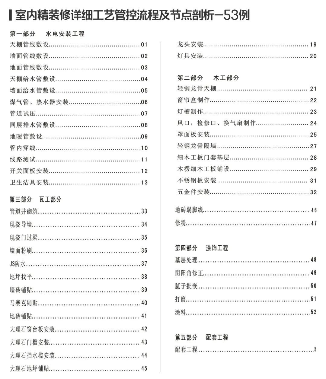
Interior finishing process control process(53 cases node anatomy) to give you a full set of engineering solutions!
Share the experience in the construction of interior fine decoration projects, and the fine decoration project construction operation process, for “hydropower, carpentry, tile, paint and supporting units” construction methods to be refined, and some nodes with on-site pictures and node highlights.
To do a good job of fine decoration, not only to control costs, rush the duration but also to protect the quality, for the project team is a great test, wherein the process index is the key to the entire project management logic! So before we begin, let’s sort out with you the entire workflow of fine decoration:
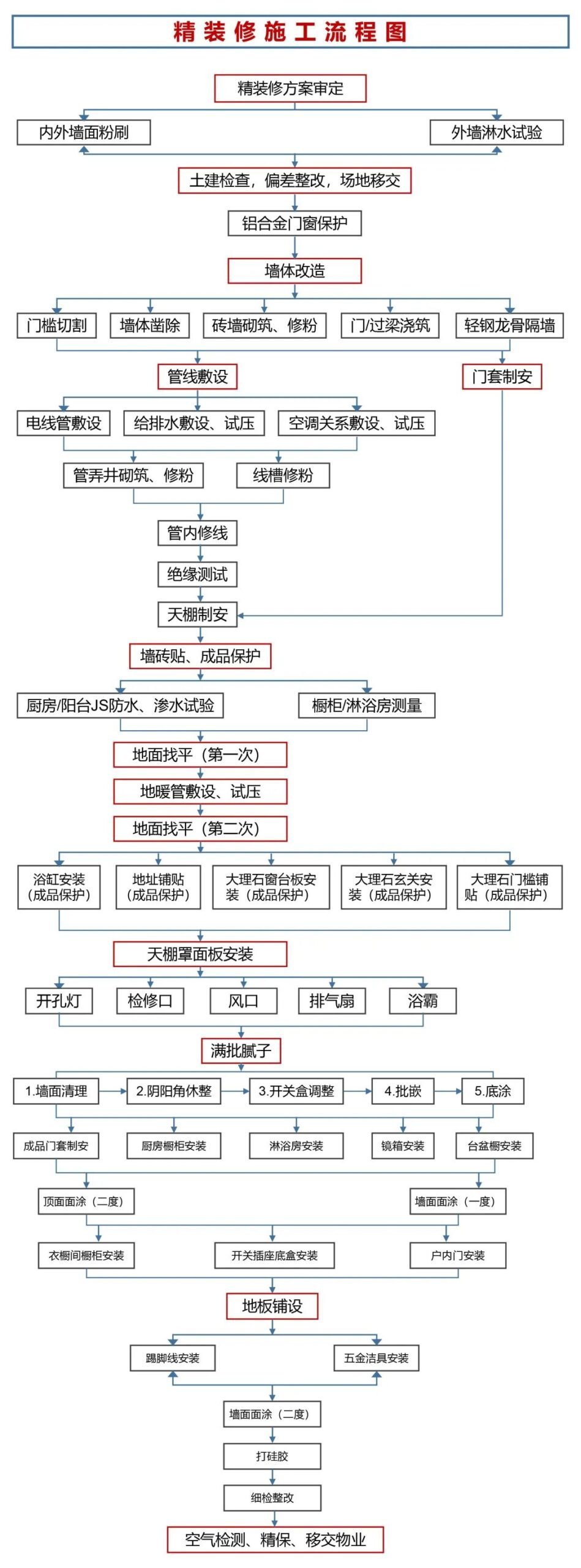

Specific process control for “hydropower, carpentry, tile, coatings and supporting unit installation projects” (downloaded in this issue of the journal at the end of this article).
01.
Hydropower installation – 18 items in total
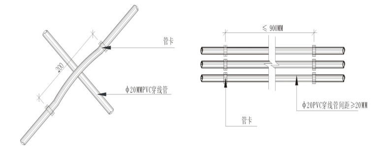
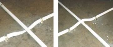
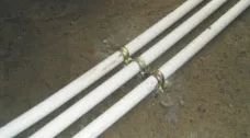
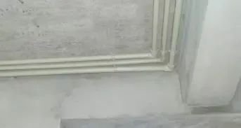
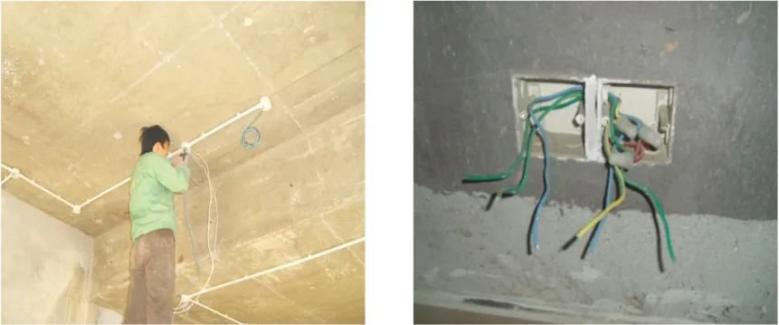
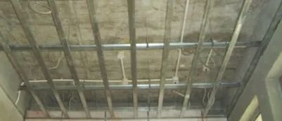
1. Roofline laying:
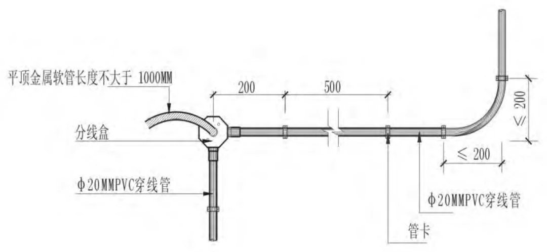
Painted pipeline node details
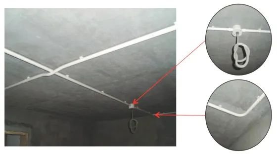
A real-life view of the roofline
Industrial control requirements:
PVC lamp headbox from the pipe card distance should be ≤ 200mm, the distance between the tube card and the tube card ≤500mm, the tube card with 6mm nylon expansion hose fixed, disabled wood will replace. PVC junction box and wire tube with cup comb glue connection. The wires drawn from the junction box are protected to the lamp position by applying metal hoses to prevent the wires from exposing to the flat top.
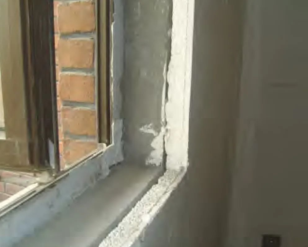
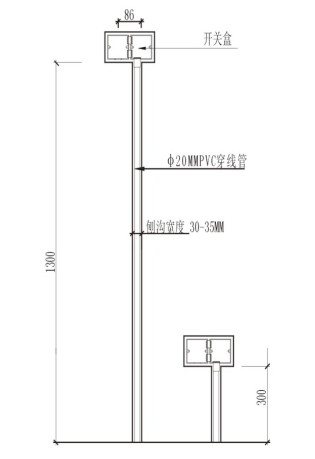
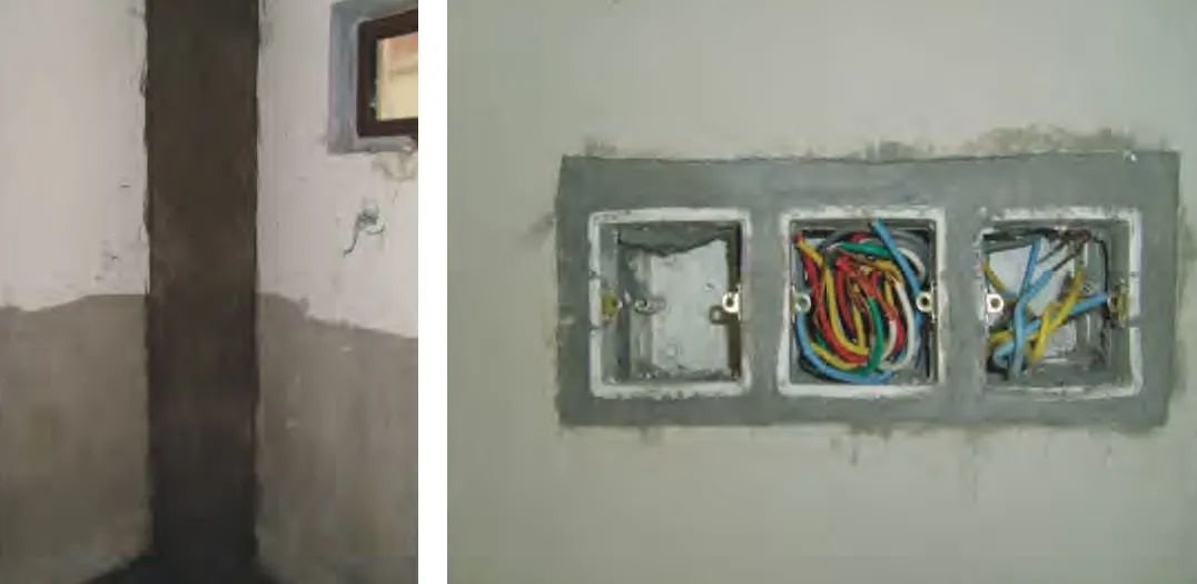
2. Wall line laying :
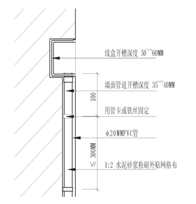
Wall pipeline slotting details
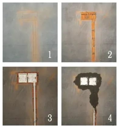
Wall line laying step
Process control requirements:
According to the electrical construction drawing, in the wall to determine the position of the switch socket and the direction of the line pipe: after the line of the trench, the depth of the side ditch should be the corresponding money pipe after the completion of the pipe distance powder layer l5mm. Groove inner tube Application of mu plum and wire fixing.
3. Ground line laying :
Ground relationship laying details
Ground pipeline crossing practices, and ground multi-pipeline practices
4. Roof water pipes are laid :
A realistic picture of the roof water pipe
Process control requirements:
Indoor water pipe laying order: “dry pipe first, branch pipe later”. Wall, roof pipeline to positioning bullet line: water pipe to the left hot right cold, hot and cold.
5. Wall water pipe laying:
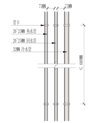
Hot and cold water pipe spacing

A real-life view of the hot and cold water pipe
Process control requirements:
The depth of the trench of the dark water pipe shall be 15mm from the powder level after the pipe is laid. And label fixed point, fixed point spacing is not greater than 600mm, the terminal fixed point is not greater than 100mmfrom the mouthpart;
6. Gas pipe, water heater installation:
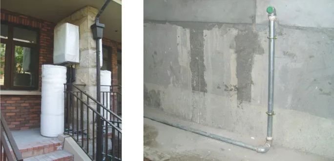
Water heater, gas pipe real picture
Process control requirements:
Gas pipes shall not be covered in dark, shall not cross the bedroom, and gas pipes that cross the ceiling shall not have joints. Gas pipe fixation needs to be fixed with a special pipe card. Tube card spacing ≤ 1200mm.
7. Pipe test pressure:
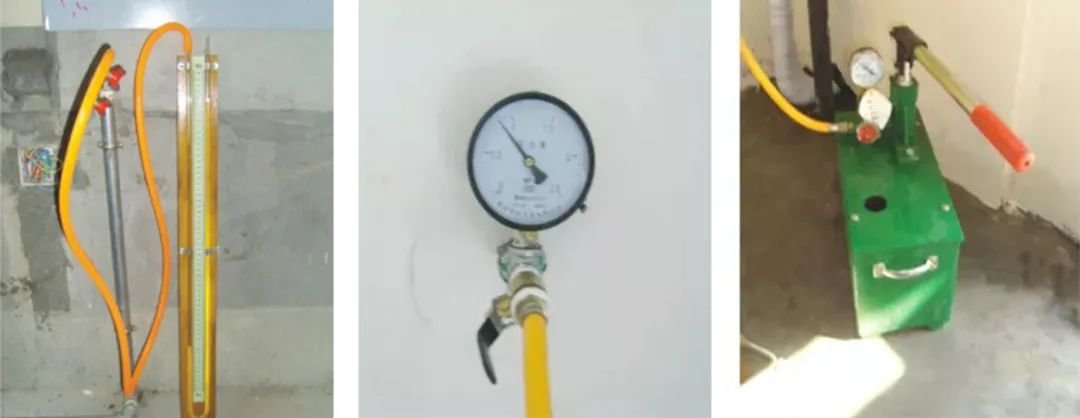
Gas pipe test pressure, water pipe test pressure
8. The same layer of drainage pipe is laid :

The same layer drainage reality picture
Process control requirements:
Drainage pipes should be temporarily sealed for the original pipe ports and ground leakage before construction to prevent debris from entering the sewer pipe. Drainpipe laid on the ground cross pipe must have a certain slope, slope size depends on the scene, generally 2% to 3%. Sewage pipes must not be connected to wastewater pipes.
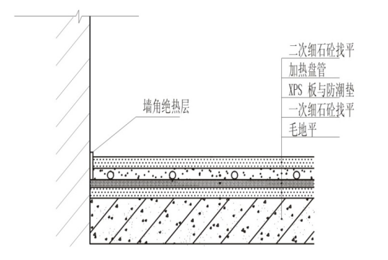
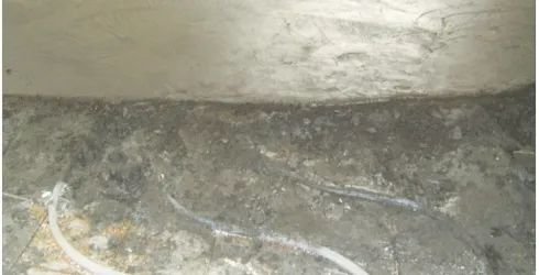
9. Underfloor plumbing:

A map of the laying of the ground heating
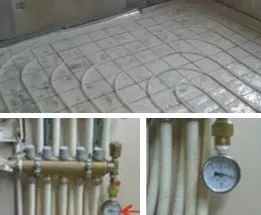
The solid plot of the ground heating laying
Process control requirements:
Installation preparation A preparation of a polyphenyl plate a spread of reflective film a roll of wire mesh, a row of pipes and installation of water divider a pressure test a mash-up one debugging
The underfloor heating pipe shall be calibrated according to the design drawings of the pipe spacing and direction of laying, should be kept straight, before laying should check the appearance quality of the tube, the tube inside must not have impurities. When the installation is interrupted or complete, the exposure should be sealed at all times. The underfloor heating pipes buried in the filling layer should not have connectors.
The loop arrangement of the underfloor heating pipe should not pass through the telescopic seams in the filling layer. Flexible sleeves not less than 400mm in length should be installed at the telescopic seam when crossing. After laying, the first test pressure inspection of the water pipe is carried out After the fine stone concrete is leveled, the second test pressure is carried out before the floor is laid.
10. Tube throughline :
A real-life view of the in-tube throughline
Process control requirements:
(1) PVC pipe installed, uniform wear wire, check whether the mouth of each pipe is complete, if there are omissions and breakages, should be filled and replaced. The reserved length of the wires in the switch box and socket box shall be 15cm, and the reserved length of the wires in the distribution box shall be 1/2 ofthecircumstantium of the distribution box.
11. Line test :
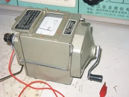
Ohm table
12. Switch panel installation:
Switch and socket node diagram

The socket reality chart
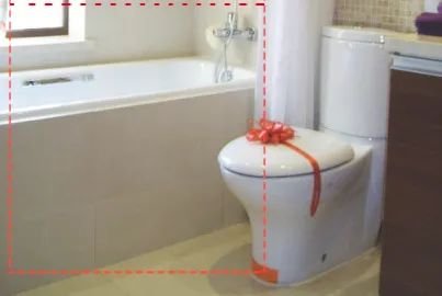
13. Sanitary Jie County Installation :
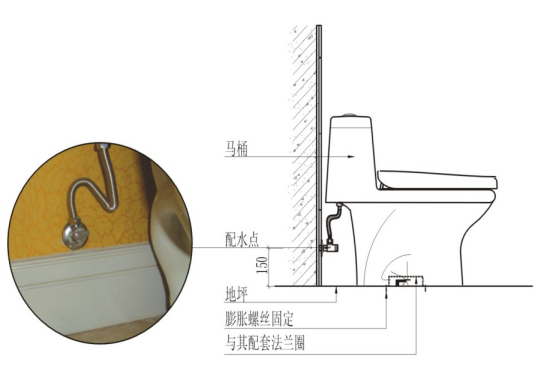
Toilet node details
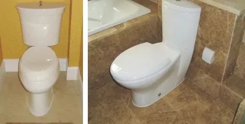
Toilet finish face reality picture
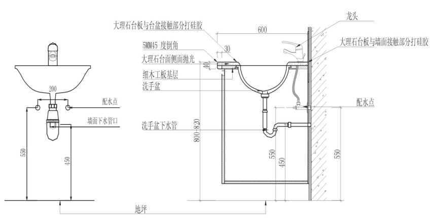
Details of the basin node
The real-life picture of the basin
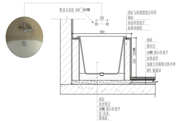
Bath profile
A real-life view of the bathtub
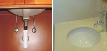
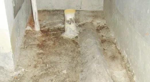
14. Ground leakage and pit pipe installation :
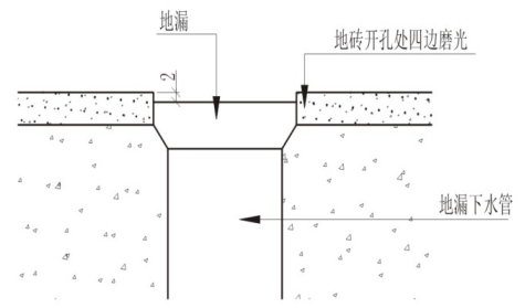
Ground leak node details
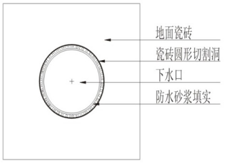
Details of the toilet outlet node
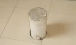
A real-life view of the toilet’s lower water mouth
15. Kitchen ground treatment:

The node details
Process control requirements:
The specific method of operation is to clean up the grassroots, the yin corner should be treated as a 20mm high R arc. Because leakage occurs in the pipe through the floor, ground leakage, sanitary ware, and kitchen and bathroom yin angle, and other parts, so pay attention to the waterproofing of the detail nodes.
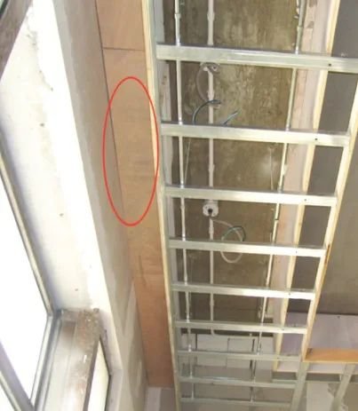
16. Kitchen line guard :

Pipeline guard node details
Toilet line guard real-life picture
17. Tap installation :
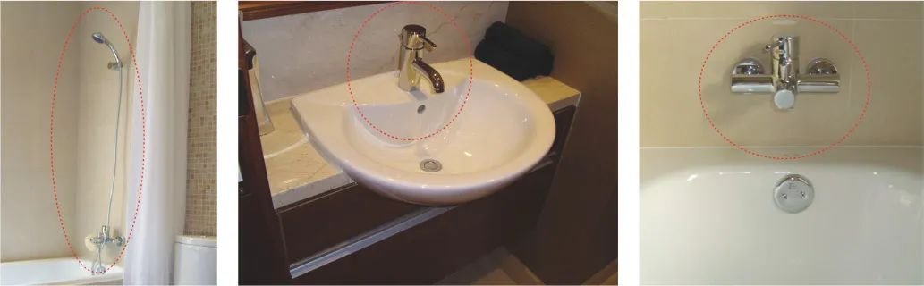
The tap is fitted with a live-view image
Control requirements:
When taking over, the left hot and right is cold, and the two tubes are 150mm and 200mmapart. Installation must be balanced, choose a suitable wrench, avoid excessive force, force installation, damage components.
18. Lamp installation:
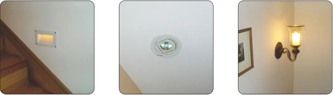
Light County Installation Live View
Control requirements:
The wires drawn from the lightbox box are protected by hoses to the lamp position to prevent the wires from exposing to the flat top. Downlight installation should be careful with the roof seam tight.
02.
Carpentry installation works – 9 items in total
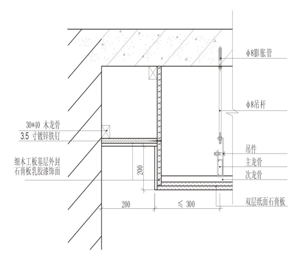
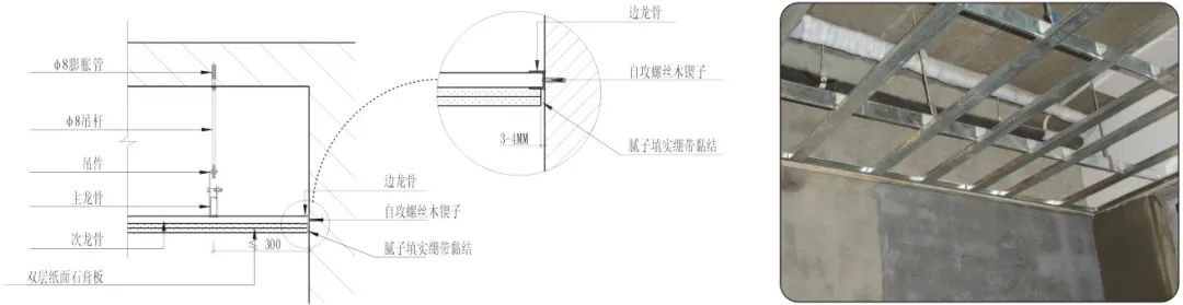
1. Light steel keel roof base:
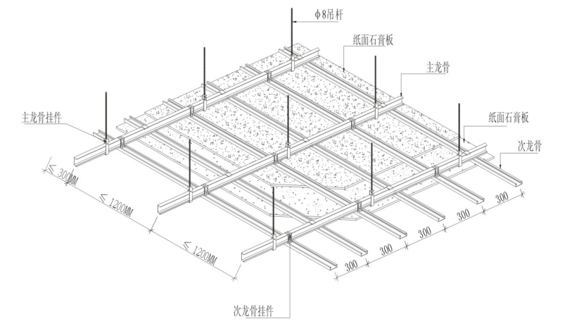
The hanging node details |
Ceiling reality picture
Process control requirements:
1) The ceiling elevation positioning bullet line, according to the design elevation in each floor of the surrounding wall bullet level control line, bullet line should be clear and accurate.
2) Rowing keel dividing line, according to the design requirements of the main and second keel spacing in the high-level line of the canopy label has been played to draw keel dividing line, should pay attention to the position of the roof downlight, the main and second keel should avoid the lamp position.
3) Install the main keel boom: To ensure the stability of the skeleton, the b8 full-tooth boom is secured by expansion bolts. After playing the high-level line of the ceiling and the keel divider line, determine the elevation of the lower end of the boom, fix the boom according to the main keel position and the spacing of the boom, and the length of the boom position should be accurate and appropriate.
4) Keel installation: using type 50 keel, keel elevation on the same horizontal line. The main keel is installed after the cable correction and then install the second keel.
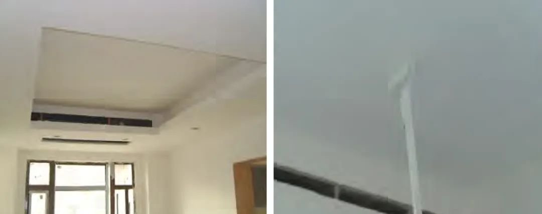
2. Curtain box production :
Curtain box construction details
Curtain box reality picture
3, lamp slot production:
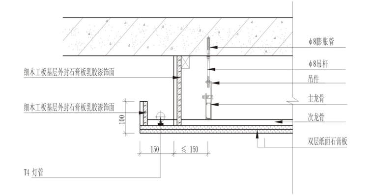
Lamp slot node diagram
Light slot reality picture
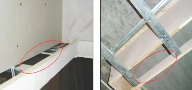
4. Air vents, access, ventilation fans, bath bar production :
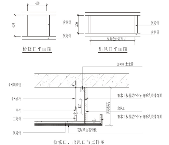
Node details
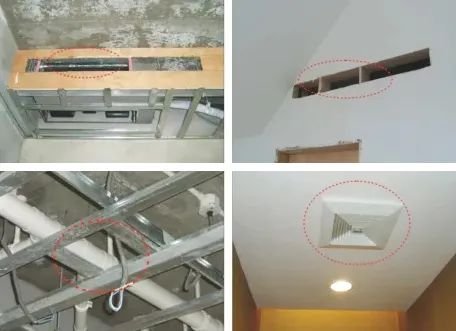
A realistic picture of the access and outlet
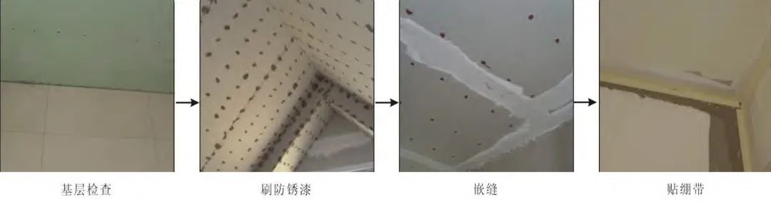
5. Cover panel installation :
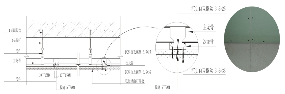
Details of the seam nodes of the board
Details of the seam nodes of the board
Process control requirements:
1) The surface layer is generally a double-layered paper gypsum board or waterproof gypsum board (FC board), the surface layer must be firmly connected with the keel, flat, gap 5-8mm.
2) The first layer of the plasterboard and the second layer of stitching should be staggered installation and glue bonding.
3) Self-tapping screws should be caught in the gypsum plate surface 0.5mm-1mm depth is appropriate, nail distance must not be greater than 200mmin the middle, screw and plate edge distance should be 10 to 15mlm.
4) The seams of the gypsum board shall be sewn according to the design requirements. The gypsum board and perimeter wall or column should have a 3mm notch, using elastic putty batch embedded. so that the plasterboard can be stretched.
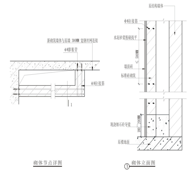
6. Light steel keel partition wall:
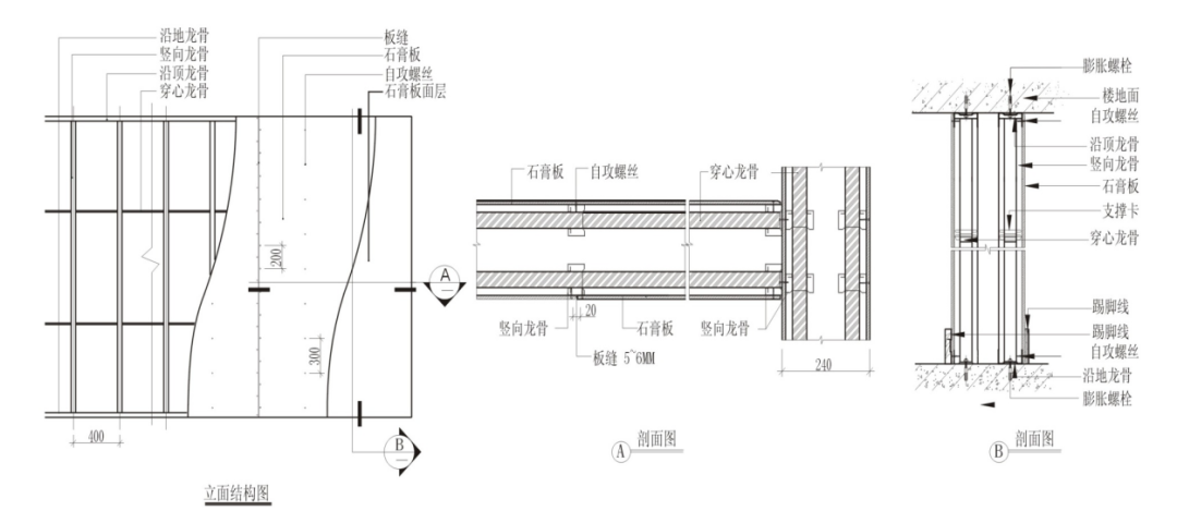
Click to see the larger picture
Process control requires:
1) According to the decorative drawings, the light steel keel partition wall site of the ground, wall, roof bullet line to determine the location.
2) Decorative engineering to make light steel keel partition wall generally uses 75 series light steel keels.
3) After adjusting the verticality by axis, install the heaven and earth keel, fixed to the roof and ground with a medium 6 x 60 U.S. solid nail, and the fixed point spacing is not greater than 400mm.
4) Wearing heart keel support card installation: cut the corresponding length of the pericardial keel according to the length of the wall, into the reserved position in the main keel, with the support card fixed firmly, pay attention to ensure that the wearing keel level, straight.
7. Carpentry plate door cover grass:
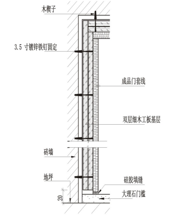
Door cover node details
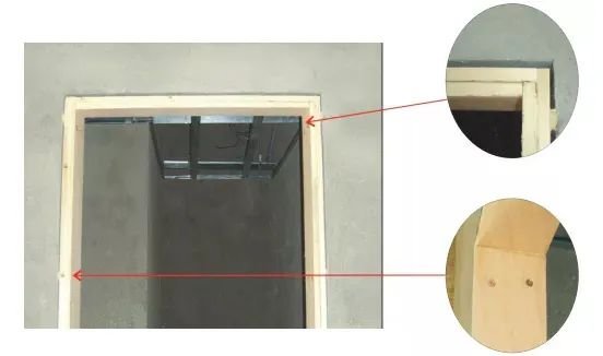
A solid picture of a wooden door cover
Process control requirements:
1) Check whether the civil reserved door hole meets the door cover size requirements, if not in line with the construction should be repaired after rectification, wooden door is set to do a good job of anti-corrosion treatment.
2) The door cover base is a double-layered carpentry board, which is pressed and molded after bonding with woodworking special glue, and the material is made according to the design size and actual thickness, and the door cover exceeds the wall by 2mm(kitchen, bathroom door cover should exceed the wall by 20mm). ), the same door frame horizontal, vertical plate uniform specifications.
3) The door cover is fixed, the pre-made door cover is fixed with 3.5 inches galvanized nails on the wooden crucifixion, the fixing needs to be hoisted to correct, the height and width of the door cover and the specified size error is not greater than 1mm.
4) The lower part of the door cover should be suspended from the ground, the bottom is 20mmabove the gross floor, the bottom of the kitchen guard cover is 10mmabove the threshold, and the lower 200mm should be moisture-proof. When there are multiple door covers on the same wall, the side of the door cover should be on the same plane. Same indoor door cover The height should be uniform. The door cover and the wall gap are sealed with a foaming agent, and the surface layer is flattened with cement mortar.
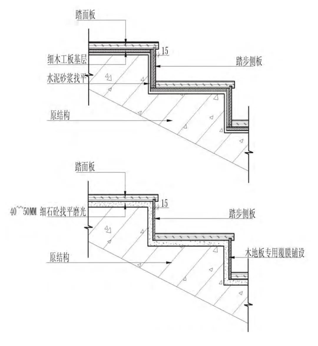
8. Woodworking board laying :
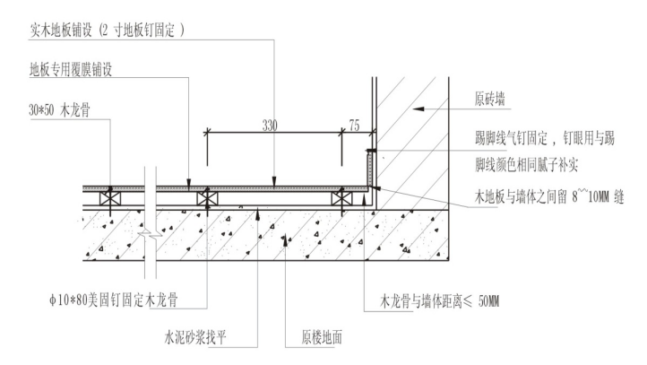
Overhead wooden floor node details
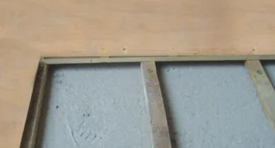
This corrugated carpentry board lays a realistic picture
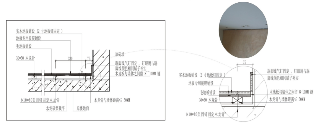
Overhead wooden floor node details
9. Stainless steel plate installation:
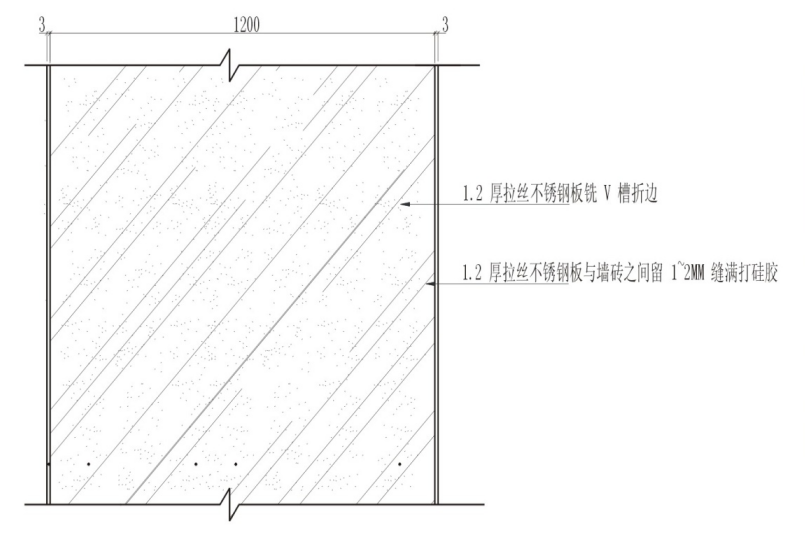
Stainless steel installation node details
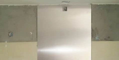
Stainless steel mounting reality picture
Process control requirements:
Wall direct: The construction is applied directly to the wall surface with various stainless steel plates. Our construction approach requires that the wall leveling layer be particularly strong and flat, ensuring that stainless steel is bonded firmly to the wall. The finish edge gap of the stainless steel plate is sealed with silicone.
03.
Tile installation works – 12 items in total
1. Pipe masonry :

A real-life picture of the pipe wall masonry
2. Now pouring the guide wall:
Now pour the wall node diagram
Now pour the wall reality picture
3. Now watering the beam:
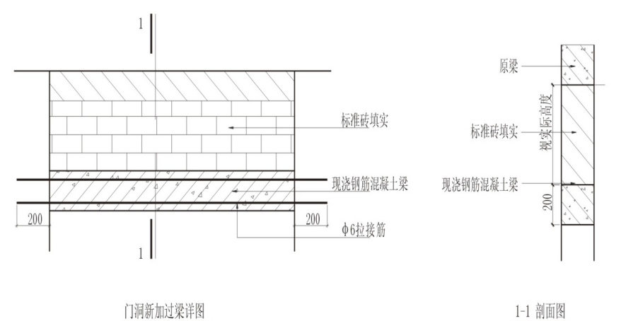
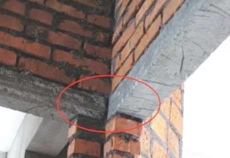
Now pouring the door over the beam reality picture
4. Wall flour brush:
5.JS Waterproof:

JS waterproof layer node
JS Paints The Real Picture
6. Flattening of the floor:
Ground leveling node graph
The ground is looking for a flat reality map
7. Wall tile stickers:
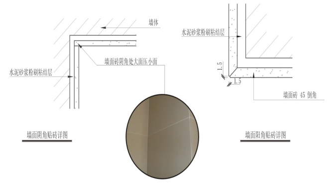
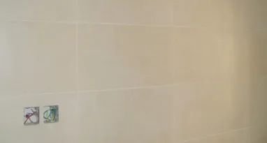
The wall tiles are covered with a realistic picture
8. Mosaic Sticker:
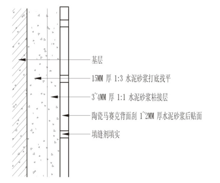
Mosaic node details
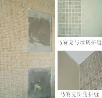
Mosaics are paved with realistic pictures
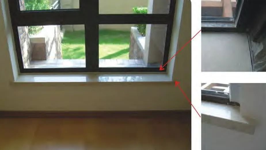
9. Marble window sill installation:
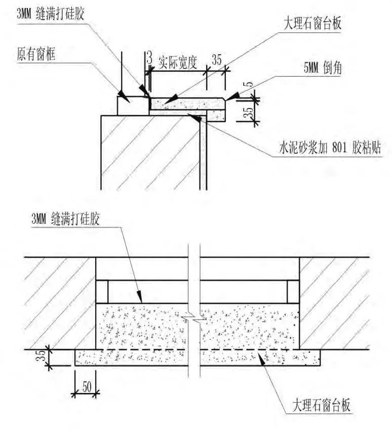
Marble window sill node
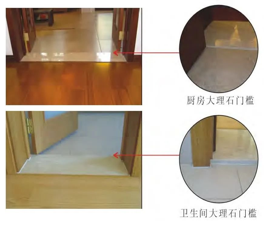
11. Marble sill installation:
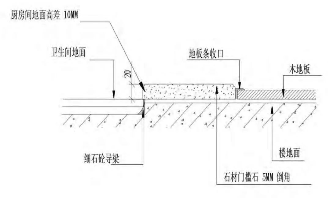
Marble threshold node
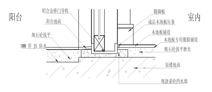
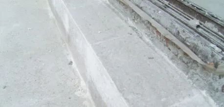
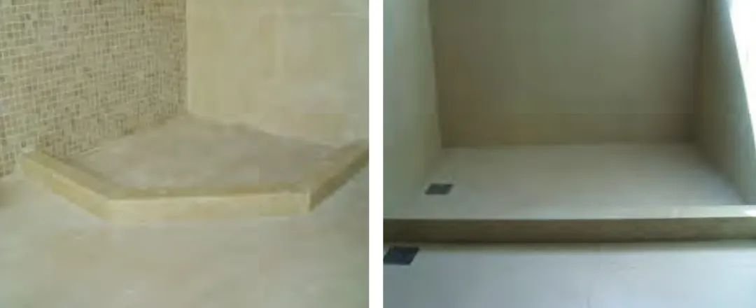
12. Marble water barrier installation:
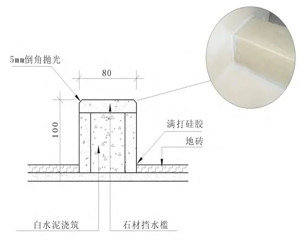
Marble water-blocking tank detailed node
04.
Painting works
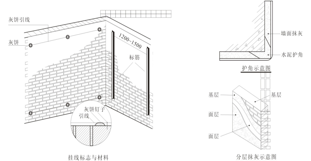
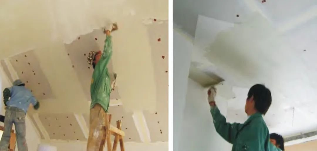
1. Powder repair:
Process control requirements:
1) When cutting the wall groove and peeling off the original paint layer, the edge must first be tilted inward with the cutting. The wall groove must remove the floating sand in the groove before placing the pipe, and the pipe-fixed fastness of the wall groove must be checked before it is sealed, and must be reinforced if loose.
3) The ash construction must be completed two to three times, not allowed to finish work once, head scraping should master the principle of the first four weeks after the middle, thickness master must not > 5mm. Cement mortar surface after the basic water collection must be used wood smear and then compacted with iron plate, such as the wall to be paved with wall tiles must be added another wood smudge process.
5) Block walls and concrete walls apply pure cement pulp before plastering to ensure bonding force. At the junction of new and old walls, the grassroots should be equipped with 300mm wide wire mesh plates to avoid cracks in the future.
7) The original wall crack repair can be peeled along both sides of the cracks 400 to 500 wide, plus 300mm wire mesh before the ash work. Walls with doors must first be embedded with 1:2 cement mortar.
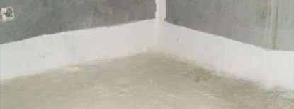
2. Grassroots treatment:
Grassroots treatment
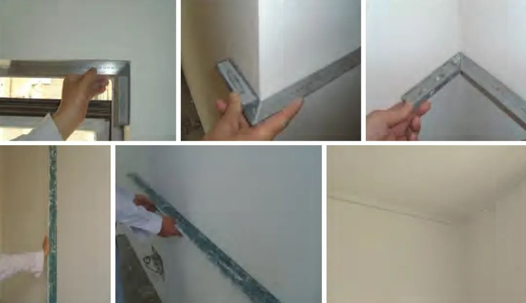
Yin and Yang angle correction
Putty batch inlay
Paint Engineering
05.
Supporting installation works
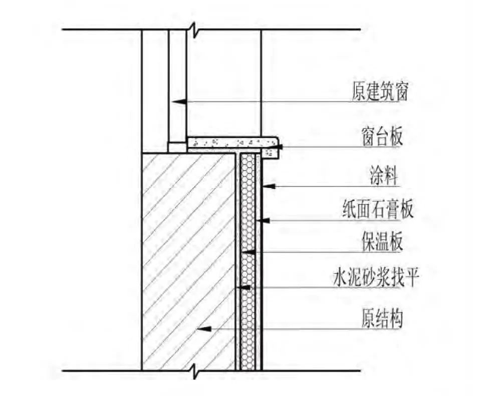
Supporting works: Insulation board node details